Reference: Guoan Zheng, Cheng Shen, Shaowei Jiang, Pengming Song, and Changhuei Yang, “Concept, implementations and applications of Fourier ptychography,” Nature Reviews Physics, 3, 207-223 (2021). (free-to-read version of the paper). Supplementary note on how to set up a Fourier psychographic imaging platform. The experimental data and code can be downloaded here: data and code download.
1. Concept of Fourier ptychography
The trade-off between resolution and the imaging field of view is a long-standing problem in traditional imaging systems. This trade-off means an imaging system can produce either an image of a small area with fine details, or an image of a large area with coarse details. Fourier ptychography (FP) is a recently developed approach for tackling this intrinsic trade-off in imaging systems, allowing researchers to have the best of both worlds. It transforms the general challenge of high-throughput and high-resolution imaging from one that is coupled to the physical limitations of optics to one that is solvable through computation. It also provides the ability to computationally correct optical aberrations post-measurement.
The original FP setup1 was modified from an LED-array microscope designed for 3D tomographic imaging2. In this setup, an off-the-shelf LED array is placed beneath a conventional upright microscope with a 2×, 0.08 NA objective lens. The LED array successively illuminates the object from different incident angles. At each angle, the system records a low-resolution intensity image that corresponds to the information from a circular pupil aperture in the Fourier domain (Box 1). The size of the aperture is determined by the NA of the objective while its offset from the origin is determined by the illumination angle. All captured images are then synthesized in the Fourier domain in an iterative phase retrieval process. The synthesized information in the Fourier domain then generates a high-resolution complex-valued object image that includes both intensity and phase properties. It also retains the original large FOV set by the low-NA objective lens1,3.
The FP method integrates two innovations in classical optics: synthetic aperture imaging4 and phase retrieval5,6. Synthetic aperture imaging was first developed at radio wavelengths. It was aimed at bypassing the resolution limit of a single radio telescope by combining images from a collection of telescopes – a feasible task if both phase and intensity information are known. FP employs the same design strategy: synthesizing the pupil aperture at the Fourier plane to bypass the resolution set by the objective lens. With FP, however, no phase is directly measured during the acquisition process, eliminating the challenges of direct phase measurements as in holography. Instead, FP recovers the missing phase from intensity measurements using an iterative phase retrieval process (Box 1). This process seeks a high-resolution complex-valued object solution that is consistent with many low-resolution intensity measurements. The original FP implementation1 employed the alternating projection algorithm for recovering the high-resolution complex sample image. In brief, the estimated solution is alternatively projected to two constraint sets in the recovery process. In the spatial domain, the captured images were used as the modulus constraints. In the Fourier domain, the confined pupil apertures were used as the support constraints. Box 1 gives a brief introduction to the alternating projection process with one incident angle, as well as an intuitive explanation about the constraints. For FP, this process is repeated for multiple images captured under different incident angles. The confined pupil aperture, as a result, will be digitally panned across the Fourier space according to the illumination angles, in effect synthesizing a large passband for the complex object (Fig. 1).
Box 1 | Phase retrieval and alternating projection
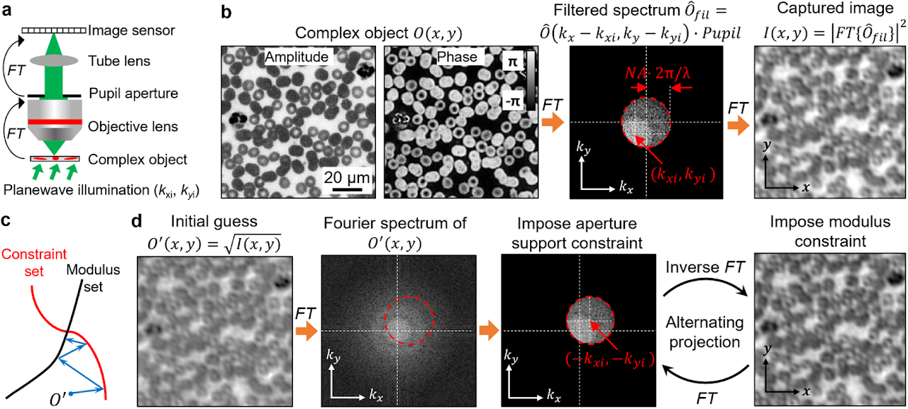
Phase information characterizes the optical delay accrued during propagation. Light detectors can only measure intensity variation of the light waves. Phase information is lost during the detection process. Measuring the phase of light waves often involves additional experimental complexity, typically by requiring light interference with a known field, in the process of holography. Phase retrieval provides an alternative to the measuring phase without requiring sophisticated interferometric setups.
We consider an optical microscope setup in panel a. In this setup, the operations of the objective and the tube lens are to sequentially perform two Fourier transforms, denoted as FT, of the object’s light waves. Panel b shows the acquisition process. First, the complexed object interacts with the tilted plane wave, generating an exit field. Second, the objective performs a Fourier transform of the resulting field. Third, the Fourier spectrum is low-passed filtered by the pupil aperture with a cutoff frequency determined by the numerical aperture (NA). Lastly, the tube lens performs the second Fourier transform of the filtered spectrum and the resulting intensity image is captured by the detector.
The phase retrieval process in this example is to recover the complex object from the intensity measurement. One effective algorithm for this problem is alternating projection5, which finds the intersection between two sets of solutions shown in panel c. The first set is all the possible object solutions that are constrained within a given support area, termed constraint set. In this example, the support area is the pupil aperture in the Fourier domain. Signals outside this area are blocked off by the aperture. To impose this support constraint, we can set the signals outside the support area to be 0s while keeping the signals inside the area unchanged. The second set is all possible object solutions that are consistent with the given intensity measurement, termed modulus set. The search for the intersection is performed by projecting the current estimate onto these two sets, as shown in panel c. In our example, projecting to the constraint set is performed in the Fourier domain by setting the spectrum values outside the shifted pupil aperture to 0. The shifted offset is determined by the illumination wavevector. In contrast, projecting to the modulus set is performed in the spatial domain by replacing the modulus of the estimated object with the measurement while keeping the phase unchanged. Panel d shows the alternating projection process. First, the initial guess of the complex object is projected to the constraint set in the Fourier domain by setting the spectrum values outside the shifted pupil aperture to 0s. Second, the updated spectrum is transformed back to the spatial domain and the object amplitude is replaced by the measurement while the phase is kept unchanged. The above two projections are repeated until the solution converges.
Box 2 | Setting up an FP experiment
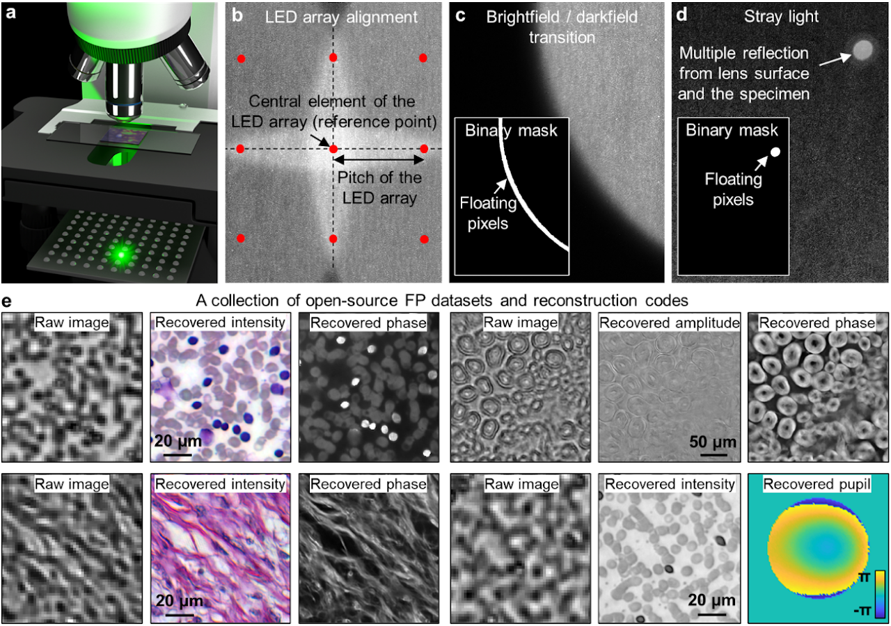
To set up a simple FP experiment, one can place an LED array under the specimen in a microscope platform, as shown in panel a. We recommend the following off-the-shelf parts for the setup: 1) LED array with 4 mm or smaller pitch (Adafruit ID: 3444, 607), 2) 2×, 0.1-NA Nikon objective and the related tube lens, and 3) 20-megapixel camera with a 2.4-µm pixel size (Sony IMX 183).
In the image acquisition process, an empty slide can be used to collect the reference darkfield images for background correction (darkfield refers to the scenario where the LED illumination angle exceeds the maximum acceptance angle of the objective). The subtraction of these reference darkfield images from measurements can reduce the impacts of ambient and stray light.
To infer the position of the LED array with respect to the specimen, we can select an LED element as the central reference point. 4 adjacent centrosymmetric LEDs are then chosen such that their incident angles are close to the maximum acceptance angle of the objective. The captured image corresponding to these 4 LEDs, thus, exhibits brightfield-to-darkfield transition features in panel b. The location and the orientation of the LED array can be estimated from these features.
In the iterative phase retrieval process, the captured images are often segmented into small tiles (e.g. 256 by 256 pixels) for reconstruction. In this way, the pupil aberration can be treated as spatially invariant across the area of each tile, and the LED illumination can be assumed to be planar. Some regions of the captured images are better to be excluded from updating the object solution. Panels c and d demonstrate two representative cases: the brightfield-to-darkfield transition region and the bright spot caused by the stray light. As shown in the insets of panels c and d, binary masks can be generated to locate these regions. When the corresponding images are used as modulus constraints in the updating process, the pixels in the masked white regions will be refrained from updating the estimated object solution7. A collection of 11 FP datasets and reconstruction codes are provided for the interested readers (Panel e)8. Supplementary note provide a simple protocol for setting up an FP experiment using off-the-shelf components.
2. FP and real-space ptychography
As suggested by its name, FP is closely related to an imaging modality termed ptychography (‘p’ is silent; here we refer to it as real-space ptychography for distinction9). Real-space ptychography is a lensless imaging technique originally proposed for solving the phase problem in electron microscopy10. The name of ptychography derives from the Greek ptycho, meaning ‘to fold’. It aspires to recover the phase information from diffraction measurements via the convolution theorem. Current implementations of this technique were brought to fruition with the help of iterative phase retrieval algorithms11-18. For a detailed discussion of the history and different implementations of ptychography, we direct the interested readers to a comprehensive article by Rodenburg and Maiden19.
Figure 1 shows the comparison between FP and real-space ptychography. Real-space ptychography typically illuminates the object with a spatially confined beam. The Fourier diffraction patterns are recorded at the far-field as the object is mechanically scanned to different x-y positions. The captured diffraction patterns are then used to recover the complex object image in the spatial domain. From Fig. 1, it is clear that both FP and real-space ptychography share the same forward imaging model. With real-space ptychography, the finite support constraint is imposed by the confined probe beam in the spatial domain while the modulus constraint is imposed by the diffraction measurement in the Fourier domain. FP, on the other hand, swaps the spatial domain and the Fourier domain by using a lens1,20. With FP, the finite support constraint is imposed by the pupil aperture in the Fourier domain while the modulus constraint is imposed by the image measurement in the space domain. For both techniques, data redundancy via aperture overlap in-between adjacent acquisitions is critical for a successful reconstruction. If no overlap is imposed, the recovery process will be carried out independently with each other, leading to the usual ambiguities inherent to the phase problem. The imaging model in Fig. 1 also suggests the use of spatially coherent light sources for both techniques. In practice, light source incoherently emits photons across a finite region. According to the Van Cittert-Zernike theorem, one solution for improving spatial coherence is to place the source far away from the sample, in effect reducing the optical flux reaching the sample. Alternatively, the finite extent of the light source can be divided into multiple coherent point sources. The resulting intensity pattern, therefore, can be treated as an incoherent summation of multiple diffraction patterns from these point sources, i.e., an incoherent mixture of coherent states. One can then model this mixture with multiple incoherent modes of the pupil in FP (spatial probe in real-space ptychography)17. In general, the partial spatial coherence of LED light source can be well addressed in both FP and real-space ptychography21.
Because of the close relationship between the real-space ptychography and the FP, conceptual innovations developed for real-space ptychography can be adopted in FP implementations. For example, the coherent-state multiplexing scheme17,18, the multi-slice modelling22, the positional correction scheme23, and the object-probe recovering scheme13,14 can be directly implemented in FP experiments. Despite the close relationship between the two techniques, there are also distinct differences between them. As summarized in Fig. 1, a key difference is that FP provides a straightforward and practical means for resolution improvement. To date, the best reported NA is ~1.6 for FP24 and ~0.4 for lensless real-space ptychography21,25. Other differences include detector dynamic range’s impact on the final image quality, differing temporal coherence requirements, sampling strategies, and initialization strategies. We also note that, there is a related implementation of angle-varied illumination for resolution improvement in electron microscopy, referred to as tilted series reconstruction26,27. To the best of our knowledge, Fourier aperture synthesising via iterative phase retrieval has not been demonstrated until FP was developed.
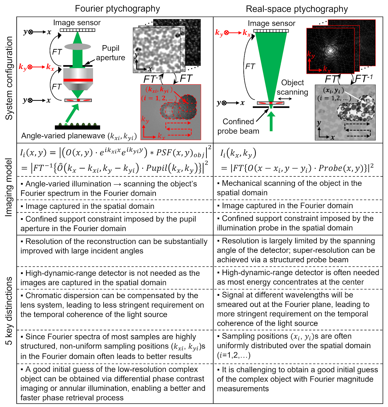
Fig. 1| Comparison between FP and real-space ptychography.
3. Implementations of FP
Table 1 categorizes different FP implementations into 4 groups. Figure 2 shows several representative schematics of these implementations.
3.1 Strategies for performance improvement
The first group of implementations is related to the performance improvement of the original LED-array microscope setup. In the following, we will discuss strategies for improving the resolution, acquisition speed, device portability, and phase imaging capability. The resolution d of the complex amplitude in an FP system is determined by both the NA of the objective lens28. It is clear that higher FP resolution can be achieved by either increasing the objective NA or using an LED array with larger incident angles24,29-32. Ou et al. demonstrated the first high-NA FP system that used a 40× 0.75-NA objective, and a maximum illumination NA of 0.7 to synthesize a system NA of 1.4529. Similarly, Sun et al. demonstrated a 1.6-NA FP system using a 10× 0.4-NA objective and a 1.2-NA oil-immersion condenser lens24.
The acquisition speed of the original FP setup is limited by a large number of image acquisitions and the relatively long exposure time for acquiring the darkfield images. To reduce the number of acquisitions, better sampling strategies can be employed by selecting or arranging the LED illumination wavevectors in the Fourier space. One example is content-adaptive illumination33-35, where a subset of illumination angles is selected based on the spectral energy distribution in the Fourier space. This strategy is most effective for specimens that have a highly structured Fourier spectrum, such as the USAF resolution target. It may be ineffective for biological samples whose frequency contents are often uniformly expanded in the Fourier space. Another strategy for reducing the number of acquisitions is to perform non-uniform sampling in the Fourier domain (left panel of Fig. 2a)36. As most signal energy concentrates at the central region of the Fourier spectrum, a higher density of sampling points ( s can be employed for the central region. For darkfield images with large incident angles, the aperture overlap between adjacent acquisitions can be reduced to 20% or less. With the same Fourier bandwidth coverage, this strategy can substantially reduce the number of acquisitions from 137 in the original FP setup to 6836. We also note that, the sampling points ( s in the original FP setup form a quasi-periodic grid in the Fourier domain. Such a periodic scan pattern is susceptible to image artifacts known as raster scan pathology13. Non-uniform sampling strategy can also address this issue by breaking the translational symmetry of the sampling points in the Fourier domain. The third example for reducing the number of acquisitions is to perform multiplexed sampling in the Fourier domain. In this case, multiple LEDs with different incident angles38,40 or different colours37,39,40 can be turned on at the same time for sample illumination (Fig. 2b). Tian et al. demonstrated a high-speed in vitro FP implementation41 using this strategy (right panel of Fig. 2b). In this implementation, an initial guess of the complex object was generated via differential-phase-contrast imaging132, which was performed by turning on half of the LED array for image acquisitions. With a good initial guess, it is possible to recover the high-resolution complex object with multiplexed darkfield measurements.
The use of the LED array in the original FP setup leads to a relatively long exposure time for acquiring the darkfield images. To improve the light delivering efficiency, the LED elements can also be angled towards the sample or arranged on a hemisphere dome (right panel of Fig. 2a)30-32. Another strategy to shorten the exposure time is to use a steerable laser beam, in place of the LED array, for sample illumination43-45. The use of laser allows the intensity to be substantially increased beyond the limitation of LEDs. To this end, Chung et al. demonstrated the use of a guided laser beam for angle-varied illumination44. The scheme is shown in the left panel of Fig. 2c, where a mirror array and a 2D Galvo scanner are used to provide planewave illuminations with centimeter beam size at diverse incidence angles. Similarly, a digital mirror device can be coded to generate angle-varied illumination at high speed (right panel of Fig. 2c)43,45. In this case, the beam size and the FOV is limited by the projection lens. For low-light applications, single-photon detection can also be employed in FP to reduce the exposure time and improve the signal-to-noise ratio133.
The FP approach can be implemented in portable and turnkey systems. For example, low-cost lenses can be used to develop high-resolution imaging systems. Dong et al. demonstrated a 3D-printed, field-portable FP microscope using a cellphone lens47. More recently, Aidukas et al. demonstrated the use of Raspberry Pi and its low-cost camera module for building an FP microscope with sub-micron resolution49. The FOV of most FP implementations discussed so far is limited by the size of the image sensor. A robotic scanning system can be integrated with FP for expanding the FOV. To this end, Guo et al. demonstrated a low-cost whole slide scanner using an LED array for sample illumination50. It can be used for both regular incoherent microscopy and coherent FP imaging.
Phase retrieval process generally requires a good initial guess. In FP, this initial guess can be created by using the captured low-resolution images with the phase set to a constant1. Over the past few years, there have been innovations on improving the initial guess. Tian et al.41 reported an improved initialization that uses the differential-phase-contrast imaging132 to generate the initial phase. Another strategy is through annular illumination40,51. In this approach, the illumination angle is close to the maximum acceptance angle of the objective, i.e., images are captured near the brightfield-to-darkfield transition region. The phase information of the specimen, especially for the low-frequency phase components, can be effectively converted into the intensity variations for detection51.
Table 1| Summary of different FP implementations
Improving the performance of the original FP implementation
- Improving the resolution: larger incident angles29-32, oil-immersion condenser lens24.
- Improving the acquisition speed: content-adaptive illumination33-35, nonuniform sampling strategy in the Fourier plane36, spectral and angular multiplexing37-40, multiplexed source coding41, symmetrical illumination42, rapid laser beam scanning43-45.
- Improving the system portability: beam steering via a low-cost liquid crystal display46, a cellphone-lens system47, a moldless-lens system48, a Raspberry Pi system49, and a low-cost whole slide scanner with LED array illumination50.
- Improving phase imaging capability: better initial guess of phase via different-phase-contrast imaging41, annular illumination40,51.
Reconstruction approaches and algorithms
- System corrections: LED intensity correction52,53, LED alignment calibration and incident angle correction53-58, correcting under- and over-exposed pixels7, joint sample-pupil recovery59-62, sample motion correction63, stray light detection64, vignetting effect65.
- Phase retrieval algorithms: stochastic gradient descent59, Gauss-Newton method with amplitude-based cost function57, adaptive step size for gradient descent66, Wirtinger gradient67-71, convex relaxation72, regularization via sparsity73,74, noise modelling and denoising68,69,75,76, stochastic proximal gradient descent77, low-rank recovery78.
- Neural network and related approaches: high-resolution image recovery from low-resolution FP measurements via deep neural networks79-84, incorporating physical model for designing the coded illumination pattern85-89, neural network model for the optimization process (also known as automatic differentiation)90-93, virtual brightfield / fluorescence staining and other unsupervised image style transfer of the FP reconstructions94.
New hardware implementations
- Aperture-scanning FP: mechanical scanning of a confined aperture61,95,96 and a diffuser97, digital scanning via a spatial light modulator60,98,99, dual-wavelength implementation for phase unwrapping96, and single-shot implementation100.
- Long-range super-resolution imaging: camera-scanning FP95,101,102.
- Reflective implementations: angle-varied illumination103-107, aperture scanning61,96.
- Multi cameras: 6108 and 96 cameras109 for parallel acquisition, Scheimpflug arrangement110.
- Single-shot implementations: diffraction grating100,111, lens array112, colour-multiplexing40.
- Translated speckle illumination for super-resolution microscopy and long-range imaging: fluorescence113-115, coherent imaging115,116, far-field speckle scanning116,117.
- X-ray imaging: pinhole scanning118, lens and detector translation118-120, Bragg configuration121.
Addressing the model limitation: 2D wave-object multiplication
- Better forward imaging model: multi-slice modelling9,122,123, diffraction tomography124-129.
- Modulating the exit wave at the detection path: aperture-scanning FP61,95-98, diffuser modulation for coherent super-resolution microscopy130,131.
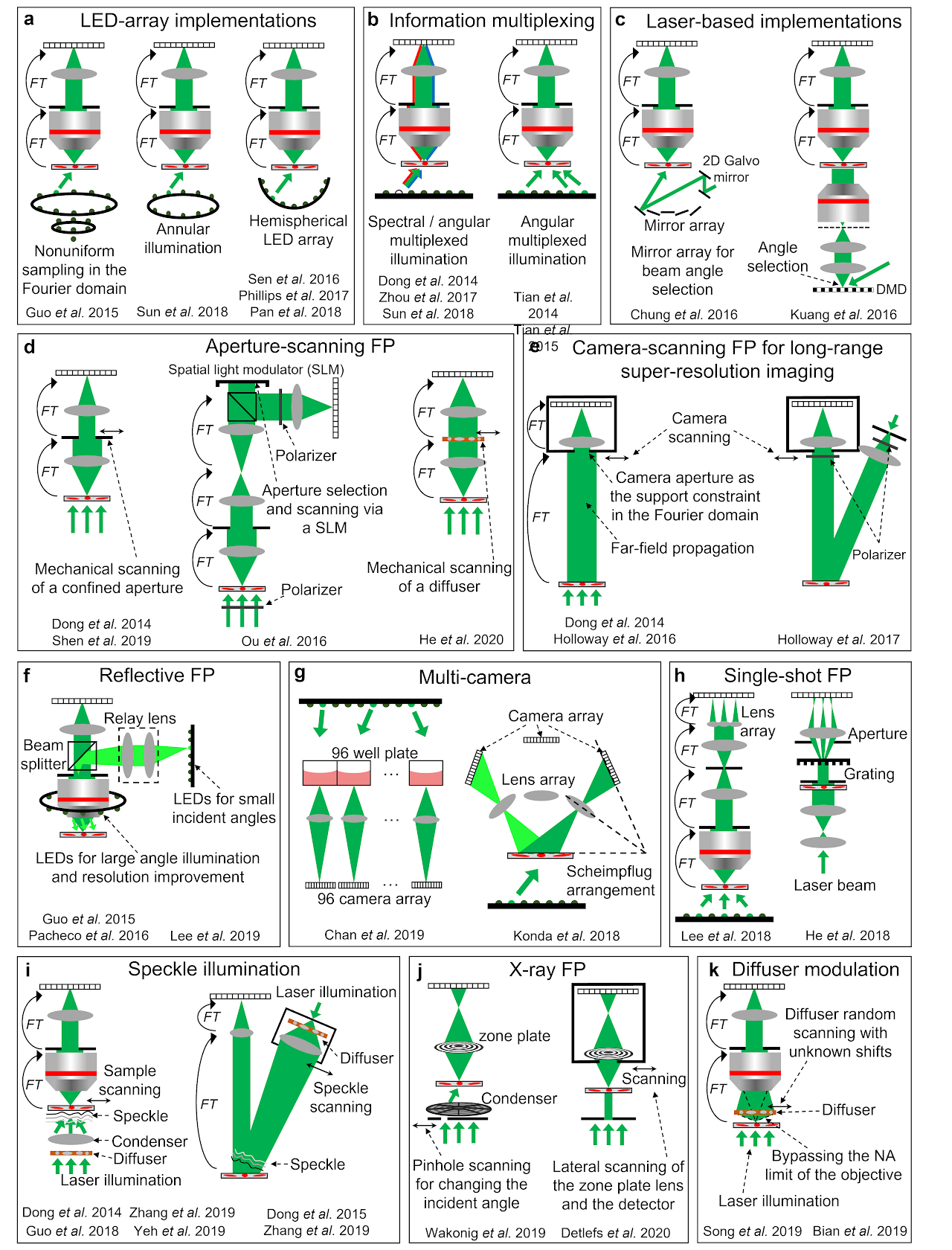
Fig. 2| Different implementations of FP.a| FP implementations using LED array, including nonuniform sampling in the Fourier space36, annular illumination for phase imaging51, and illumination via a hemispherical LED array30-32. b| Information multiplexing for FP, where multiple LEDs with different colours37,39,40 and / or different incident angles38,40,41 can be turned on at the same time for sample illumination. Properly chosen multiplexed angles can shorten the acquisition time for in vitro imaging41. c| FP via laser-based illuminations, including the use of a mirror array44 and a digital mirror device43 for rapidly changing the incident angle. d| Aperture-scanning FP. An aperture61,95,96 or a diffuser97 can be scanned to different positions at the Fourier plane. The aperture scanning process can also be performed using a spatial light modulator98 or a diffraction grating100 without involving mechanical scanning. e| Camera-scanning FP. By placing the object at the far-field, the lens aperture naturally severs as an aperture constraint at the Fourier plane. By scanning the lens and the detector to different lateral positions, a super-resolution complex object image can be synthesized in the Fourier plane95,101,102. f| Reflective FP, where light is delivered through the epi-illumination path103-105. An LED ring array can be placed outside the objective for further resolution improvement103,106. g| Multi-camera scheme for parallel acquisition108-110. h| Single-shot FP using a lens array112 and a grating100,111. i| A translated speckle pattern, i.e., a coherent sum of different planewaves, can be used for sample illumination113-117. j| X-ray FP via pinhole scanning118 and lens translation118,119. k| A diffuser at the detection path can be used to modulate the exit wavefront of the complex object, in effect bypassing the NA limit of the objective130,131. This scheme can address the 2D model limitation of FP and image 3D thick samples.
3.2 Reconstruction approaches and algorithms
A successful FP reconstruction relies on an accurate imaging model of the optical system. 3 common system imperfections of an FP setup can be corrected in the iterative reconstruction process: 1) LED intensity variations, 2) incident angles of the LED elements, and 3) pupil aberrations.
For correcting LED intensity variations, Bian et al. demonstrated the use of an image-quality metric to update the LED intensity during the iterative reconstruction process52. The same metric can also be used to recover the Zernike modes of pupil aberration. For correcting incident angles from different LED elements, simple alignment of the LED array can be performed following the procedure discussed in Box 2. This alignment procedure is often sufficient for LED arrays that have a well-defined pitch. For other illuminators without a well-defined pitch, further refinement of the illumination wavevector is needed in the iterative recovery process53-58. This wavevector refinement process is similar to the positional correction process in real-space ptychography23. For pupil aberration correction, one can directly measure the spatially varying aberrations using a calibration target134. Another solution is to jointly recover both the object and the pupil in the iterative process59. Field-dependent nature of the optical pupil can also be leveraged for a more robust full-field aberration recovery62.
Different phase retrieval algorithms have also been implemented and tested for the FP platform. Table 1 summarizes some of these developments. Despite its simplicity, alternating projection remains an effective algorithm for phase retrieval. More advanced optimization strategies for ptychographic phase retrieval have been discussed by Chao and Marchesini et al.135 in a wide-ranging survey covering conjugate gradient, Newton-type second-order optimization, set projection approaches, and the relaxed average alternating reflections method. Yeh et al.57 has performed a comprehensive review of first- and second-order optimization approaches for FP datasets. It was shown that the second-order Gauss-Newton method with amplitude-based cost function gave the best results in general. In practice, given a carefully conducted FP experiment with reasonably clean data8, the phase retrieval process is typically well conditioned and amenable to solution by any optimization technique – from alternating projection to nonlinear heavyweights.
Another trend of algorithm development related to FP is the employment of data-driven approaches or neural networks in the imaging and reconstruction process. These developments can be categorized into 4 groups. The first group focus on inferring the high-resolution intensity and/or the phase images from the low-resolution FP measurements79-84. For example, Nguyen et al.79 and Zhang et al.84 demonstrated the use of deep neural networks to produce high-resolution images from FP raw measurements. More recently, Xue et al. demonstrated the use of a Bayesian network to output both the high-resolution phase images and the uncertainty maps that quantifies the uncertainty of the predictions82.
The second group focuses on incorporating the physical model into the design of the network85-89. The training of the network can jointly optimize the physical parameters used in the acquisition, such as the coded illumination pattern of the LED array. Horstmeyer et al. demonstrated the use of a neural network to jointly optimize the LED array illumination to highlight important sample features for classification task88. Kellman et al. demonstrated a framework to create interpretable context-specific LED source patterns for FP illumination89.
The third group of developments is to model the forward FP imaging problem using neural networks and perform optimization via a network training process90-93. This process is also termed automatic differentiation or algorithmic differentiation, where derivatives can be efficiently evaluated based on the forward model136. For FP, the complex object can be treated as the learnable weights of a convolutional layer. The output of the network can be modeled as the loss function one aims to minimize. Different solvers and acceleration strategies from machine-learning libraries can then be adopted in the optimization process.
Lastly, the recovered image of FP can be passed through a neural network for further improvement. For example, virtual brightfield and fluorescence staining can be performed on FP recovered images without paired training data94. Coherent artifacts of FP reconstructions can also be reduced in this unsupervised image translation process.
3.3 New hardware implementations
LED-array microscope is not the only approach for implementing FP3. Various hardware-based FP schemes have been reported in the past years. We will discuss 7 representative examples in the following. The first example is aperture-scanning FP, where the specimen is illuminated by a fixed planewave and an aperture is placed at the Fourier plane of the optical system (Fig. 2d). By translating the aperture to different lateral positions in the Fourier plane, images can be captured and synthesized in the Fourier domain to perform FP reconstruction. The key innovation of this scheme is that the recovered image depends upon how the complex wavefront exits the sample instead of entering it. Thus, the sample thickness becomes irrelevant during reconstruction. One can back-propagate the exit wave to any plane along the optical axis for 3D imaging. Dong et al. first demonstrated this scheme by using a mechanical stage to translate the aperture (left panel of Fig. 2d)95. Ou et al. later adopted a digital scanning scheme using a spatial light modulator (middle panel of Fig. 2d)98. Other related development includes scanning a diffuser at the Fourier plane (right panel of Fig. 2d)97, dual-wavelength implementation for phase unwrapping96, and single-shot implementation using a grating100.
The second example is camera-scanning FP for long-range super-resolution imaging95,101,102. In this approach (Fig. 2e), the specimen is placed at the far-field and a photographic camera is used to capture images. Far-field propagation of the light waves corresponds to the operation of a Fourier transform. As such, the lens aperture placed at the far-field serves as a confined aperture constraint in the Fourier domain. By scanning the entire camera to different positions, one can capture multiple images corresponding to different circular apertures at the Fourier plane. These images can then be synthesized to form a super-resolution exit wavefront of the object. The final resolution is not determined by the lens aperture. Instead, it is determined by how far one can translate the camera. In the original demonstration, Dong et al. first experimented with a transmission mode (left panel of Fig. 2e)95. Holloway et al. later demonstrated it in a reflection mode for imaging diffused objects (right panel of Fig. 2e)101.
The third example is reflective implementations61,96,103-107. Angle-varied illumination in the original FP setup can be implemented in the epi-illumination arm in a reflection mode. A LED ring can be mounted outside the objective lens for sample illumination with large incident angles103,106. Other related developments include an off-axis configuration with angle-varied illumination107, and the implementation of aperture-scanning FP in a reflection mode61.
The fourth example is multi-camera implementation. Chan et al. demonstrated a high-throughput screening system using 96 repeating low-cost microscope units (left panel of Fig. 2g)109. This platform can image the entire 96-well plate at a rate of 0.7 frames per second. Another configuration was reported by Konda et al., where a camera array was arranged according to the Scheimpflug principle (right panel of Fig. 2g)110. Using multiple cameras in an FP platform has the potential to substantially increase the imaging throughput.
The fifth example is the single-shot FP implementation shown in Fig. 2h. Lee et al. demonstrated a single-shot FP scheme based on a lens array and the angular multiplexing strategy (left panel of Fig. 2h)112. By placing the lens array at the Fourier plane of the objective lens, multiple intensity profiles can be collected in a single shot. Similarly, single-shot implementations can also be achieved via a diffraction grating100,111 (right panel of Fig. 2h) and colour-multiplexed annular illumination40. These different implementations essentially trade off the imaging FOV to achieve the single-shot capability.
The sixth example is the speckle illumination scheme shown in Fig. 2i. Here the speckle pattern on the specimen can be considered as an amalgamation of localized phase gradients, each approximating a plane wave incident at a different angle. A lateral translation of the speckle or the object causes a given region of the specimen to be illuminated by a different phase gradient, similar to the original angle-varied illumination concept in FP. One key distinction is that the translated speckle illumination scheme can be used for both coherent and incoherent imaging. When it is implemented for incoherent fluorescence imaging, it is conceptually similar to structured illumination microscopy137. The final archivable resolution is jointly determined by the NA of the objective lens and the feature size of the speckle pattern. Dong et al. first demonstrated this scheme for fluorescence imaging beyond the diffraction limit of the employed objective lens113. Guo et al. further demonstrated the use of a high-NA condenser to generate speckle patterns and a low-NA objective lens to acquire fluorescence images114. A 4-fold resolution gain was achieved for a fluorescence microscope setup and a 13-fold resolution gain was achieved for imaging through a low-pass diffusing layer. More recently, this concept has been extended to coherent imaging systems115,116. Zhang et al. used a 0.12-NA objective lens for image acquisition and achieve a synthetic NA of 0.85 for the reconstructed images (left panel of Fig. 2i)116. Interestingly, the translated speckle scheme can also be used for long-range super-resolution imaging. As shown in the right panel of Fig. 2i, a translated speckle pattern is projected on the remote objects and a regular photographic lens is used for image acquisition. Based on the modulation process of the projected speckle pattern, the otherwise inaccessible high-resolution object information can now be encoded into the captured images. This scheme has been validated for both coherent116 and incoherent long-range imaging settings116,117. Up to 7-fold resolution improvement has been experimentally demonstrated116.
Lastly, the FP method can be implemented in coherent X-ray microscopy for super-resolution nano-scale imaging118-121. Figure 2j shows two representative schemes of X-ray FP. The first one employed a scanning pinhole to select different illumination angles from a condenser’s different subfields118. The resolution of this scheme remains limited by the combined NA of the condenser and objective. The second scheme scans both the objective lens and detector through the diffraction beam118-120. It is conceptually similar to the camera-scanning implementation in Fig. 2e. For X-ray imaging, scanning the lens and the detector avoids the complexity of keeping the illumination constant while changing the incident angle. The achievable resolution is limited by the scan range, which extends the NA of the objective, in effect forming a synthetic lens and exceeding the NA of any available X-ray optics. The X-ray FP experiment also exhibits unexpected high dose efficiency compared to the regular transmission X-ray microscopy118. More recently, a Fourier synthesis strategy similar to FP has also been implemented in a Bragg coherent X-ray diffraction imaging experiment121. Resolution improvement in 3D has been demonstrated for crystalline materials.
3.4 Addressing the model limitation
In the forward imaging model of FP discussed in Box 1, the complex object is multiplied with the incident planewave before passing through the low-pass microscope system. This multiplication process assumes the object section is infinitesimally thin. For any practical object, tilting the illumination planewave would change the spectrum of the object rather than just shifting it in the Fourier space. In a wave optics picture, tilting the illumination would rock the Ewald sphere around the origin. The objective lens lets through a solid angle of scattered beams that subsequently form an image at the detector plane. As such, each captured image corresponds to a spherical cap of the Ewald sphere in the Fourier space. These spherical caps do not span a single 2D plane in the Fourier domain. There are two strategies to address this problem.
The first strategy is to adopt a better forward imaging model by considering the 3D nature of the object. Multi-slice modelling, originally proposed for electron microscopy138, is one example of this strategy and it has shown great success in real-space ptychography22,139. In this approach, the 3D object is represented by a series of 2D thin slices separated by a certain distance. The incident wave from the light source multiplies with the first layer to form an exit wave. The exit wave is then propagated to the second layer, where it forms a new incident wave. This process goes through the whole specimen. Tian et al.122 and Li et al.9 have demonstrated the use of multi-slice modelling to image 3D specimens using an FP microscope setup. Its advantage is that it does not make any weak or single-scattering approximations. The serial scattering from each slice accounts for multiple scattering effect in the forward direction. Backscattered light has not been considered in current implementations.
Another approach to account for the 3D nature of the object is diffraction tomography. In this approach, the object is represented by 3D scattering potential. Under the first-order Born or Rytov approximations, the captured images in an FP microscope can be used to update the corresponding spherical cap region of the 3D scattering potential in the Fourier domain. Horstmeyer et al. reported the first implementation of diffraction tomography with FP124. Zuo et al. further employ darkfield measurements with large illumination NA to demonstrate a high-throughput FP diffraction tomography platform.
Despite these successes, isotropic resolution remains elusive for these two methods due to the missing cone problem. Specifically, the 3D coherent transfer function of an imaging system under single or weak scattering approximations has a donut shape due to the limited aperture. The missing frequency near the origin along the kz direction in the Fourier domain results in a loss of spatial resolution along the z axis. It has been shown that multiple scattering can mitigate the missing cone problem, hence the multi-slice model may perform better in principle123. Computationally filling in the missing cone via some priors is also a possible strategy for both approaches. Similarly, a better forward imaging model can bring in reconstruction with higher fidelity. Thus, future developments include a multi-slice model considering backward scattering and a diffraction tomography model considering multiple scattering. A challenge for both approaches is, perhaps, the high computational demand in the reconstruction process, which often can take hours or days to recover the full 3D volume.
The second strategy for addressing the 2D modelling problem in FP is to keep the illumination angle fixed and perform modulation at the detection path. In this case, the recovered complex image represents the exit wavefront of the object. The thickness of the object is irrelevant in the modelling. The aperture-scanning and camera-scanning FP are two examples of this strategy (Fig. 2d and 2e). For aperture-scanning FP, however, the achievable resolution is limited by the NA of the first objective lens. A recent development to address this resolution limitation is to translate a thin diffuser in-between the specimen and the objective lens, as shown in Fig. 2k130,131. In this approach, the diffuser serves as a thin scattering lens for lightwave modulation. The multiplication process between the object and the tilted planewave in the original FP setup now becomes the multiplication between the object exit wavefront and the thin diffuser profile. This multiplication process allows the otherwise inaccessible high-resolution object information to be encoded into the captured images. To this end, Song et al. demonstrated a 4.5-fold resolution improvement over the diffraction limit of the objective lens using this approach130. It was also shown that a 4-fold resolution gain can be achieved with as few as ~30 raw images.
4. Applications of FP
4.1 Quantitative phase imaging in 2D and 3D
In biomedical imaging, unlabelled specimens are often inherently transparent. Thus, phase provides a complementary contrast mechanism to reveal the detailed structures that are otherwise invisible in brightfield images. Over the past two decades, quantitative phase imaging (QPI) has emerged as a valuable tool for investigating various weakly-scattering and -absorbing specimens.
The QPI capability of FP was first reported by Ou et al.140. It has been shown that the recovered phases of different samples match with the results of phase-shifting digital holography. QPI applications on a variety of biological samples have emerged since then. Figure 3a shows the FP recovered phase image of a blood smear140,141, from which phase-gradient and gradient-magnitude images can be generated post-measurement. Figure 3b shows the recovered phase images of live HeLa cell culture using the in vitro FP platform41. Similarly, Fig. 3c shows the high-speed QPI results of live HeLa cell culture using the annular illumination scheme51, where 4 images corresponding to 4 annular illumination angles were acquired and used for FP reconstructions.
QPI via FP also find applications in 3D microscopy. The refractive index distribution of a biological sample can be used as intrinsic imaging contrast for label-free and quantitative bioimaging. Traditional diffraction tomography requires an interferometric setup to measure the 2D holograms at each illumination angle. FP can be integrated with the diffraction tomography framework to recover 3D scattering potential from intensity-only measurements124. Figure 3d shows the recovered 3D refractive index distribution of live HeLa cell culture using the Fourier ptychographic diffraction tomography approach127.
Another application of QPI is optical metrology, where topographic maps of 3D surface can be generated by measuring spatially varying phase retardation. Figure 3e shows the recovered topographic map using the aperture-scanning FP under the reflection mode96. To address the phase wrapping problem, dual-wavelength reconstruction was employed to eliminate the phase ambiguity. The line traces in Fig. 3e show a 1.8-μm height difference on a topographic surface, with a measurement error of a few nanometres.
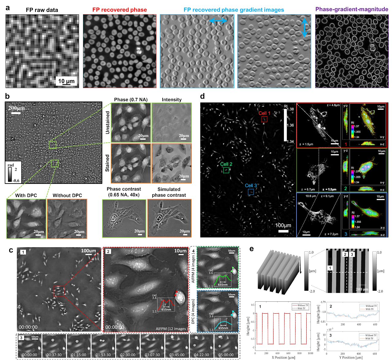
Fig. 3| Quantitative phase imaging in 2D and 3D. a| QPI of a blood smear140,141. The recovered phase can be further used to generate phase-gradient and phase-gradient-magnitude images. b| Recovered phase images via the in vitro FP implementation41, where the initial phase is generated by differential-phase-contrast imaging. c| QPI via annular illumination51, where low-frequency phase information can be effectively converted into FP intensity measurements. Cell mitosis and apoptosis events can be captured at a frame rate of 25 Hz. d| Fourier ptychographic diffraction tomography127, where 3D refractive index of the cell culture is recovered from FP intensity measurements. A 390 nm lateral resolution and 899 nm axial resolution was achieved across a 10× FOV of 1.77 mm2. e| Topographic map of a 3D surface via FP phase imaging, where two wavelengths are employed to address the phase wrapping problem96.
4.2 Digital pathology and cytometry
In a conventional microscope platform, users need to constantly adjust the axial stage to bring the sample into focus when moving across different FOV of the sample. FP address this issue by using a digital refocusing process, where a phase factor is introduced in the objective’s pupil function to correct for the sample defocus. This simple correction enables FP to extend the depth of field to ~0.3 mm1, two orders of magnitude longer than the conventional platform with a similar NA. To recover an all-in-focus image using FP, the entire image can be divided into many small segments, which can be digitally refocused and stitched together afterward.
The combination of wide FOV, high resolution, and the capability of digital refocusing post-acquisition makes FP a promising candidate for digital pathology, where digital images of stained histology slides are acquired and used for diagnostic purposes. The recovered phase information from FP further provides valuable information about the sample’s local scattering and reduced scattering coefficients, which may benefit pathology diagnosis and single-cell analysis (Fig. 4a)142. One challenge of adopting FP for digital pathology is the coherent imaging nature of the technique. The recovered FP image may contain coherent artefacts that affect the colour accuracy compared to the regular incoherent images. It is possible to apply unsupervised image-to-image translation to convert the FP constructions to the style of regular incoherent microscopy94. Figure 4b shows the recovered color and fluorescence images by virtually staining the FP reconstructions. The appearance of these network outputs is similar to those captured using regular incoherent microscope platforms.
FP can also find applications in high-throughput cytometry. For example, circulating tumour cells are recognized as a candidate biomarker with strong prognostic and predictive potential in metastatic disease. Figure 4c shows the full FOV colour image of the entire microfilter containing captured tumour cells143. Another example is high-content screening using multi-well plate108,109. Figure 4d shows a parallel microscopy system that is capable of simultaneous imaging all wells on a 96-well plate via FP. The system can also perform fluorescence imaging at the native resolution of the 96 objectives. Similarly, cell analysis can also be performed on the FP recovered high-content images for disease diagnoses. Figure 4e shows the recovered phase image of a blood smear using a high-NA FP system24. The phase information can be used to identify, for example, malaria-infected cells29. It is also possible to optimize the illumination pattern to improve the accuracy of malaria-infected cell classification87.
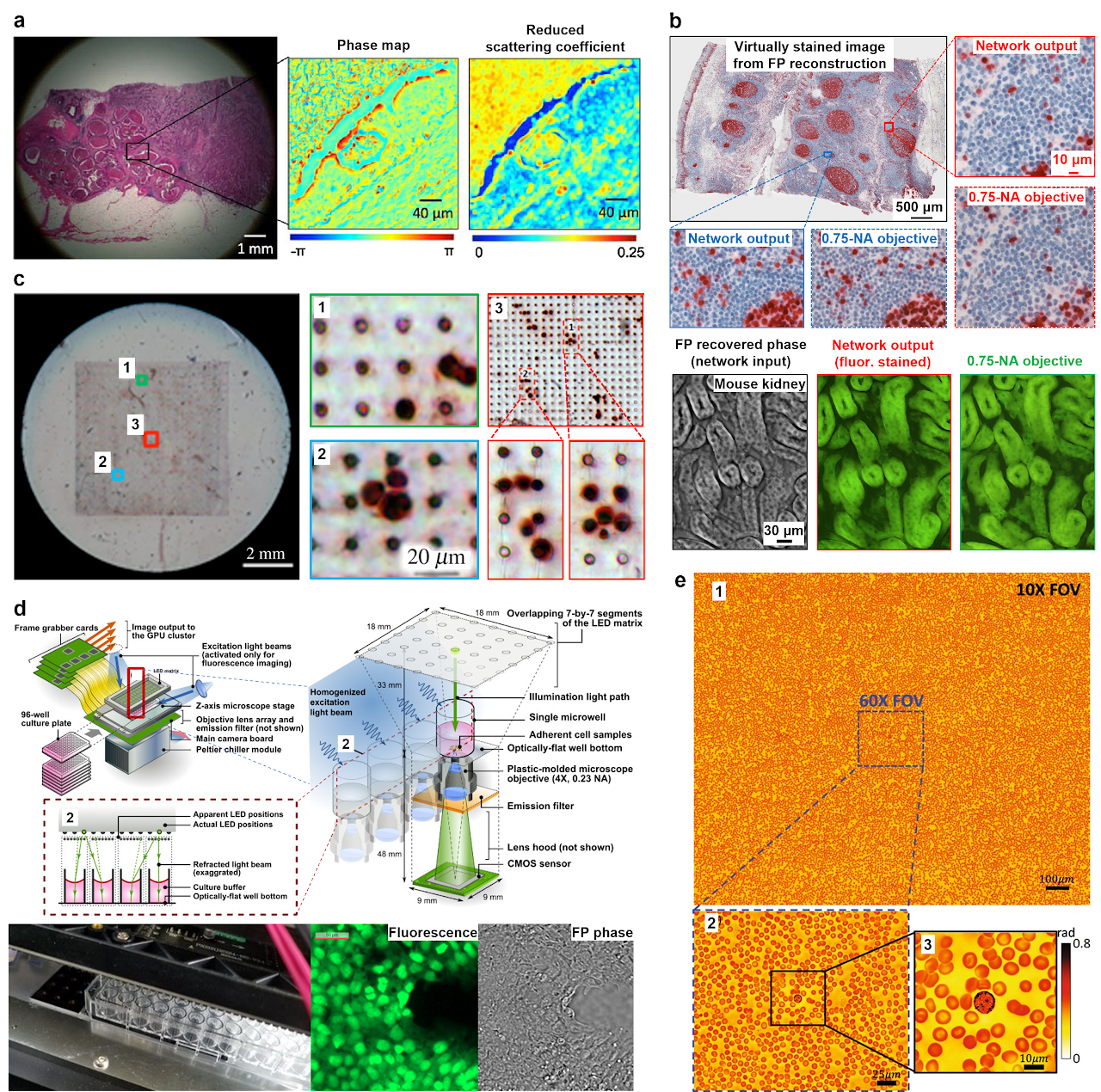
Fig. 4| Digital pathology and high-throughput cytometry via FP. a| FP can generate large FOV and high-resolution image of pathology slides59,142. b| Virtual colour and fluorescence staining of FP reconstructions via unsupervised image-to-image translation94. c| Full FOV colour image of the entire microfilter containing captured tumour cells143. d| Parallel FP system that is capable of simultaneous imaging all wells on a 96-well plate109. e| High-resolution recovered phase of a blood smear for cell analysis24.
4.3 Aberration metrology, surface inspection, and X-ray nanoscopy
As first demonstrated by Ou et al., FP can correct optical aberrations through computational post-measurement processing59. An improved version of FP with a rigorous aberration model was recently proposed by Song et al62. Instead of recovering pupil function individually for each tile, it considers the field dependency across the entire FOV, in effect reducing the degrees of freedom in the optimization process. This approach provides an effective tool for measuring aberrations of an optical system. Figure 5a shows recovered complex objects and the pupils using this approach. The aberration metrology ability of FP also makes it suitable for settings where optically reducing aberration is unattainable, such as in situ aberration correction for cellphone lens47, moldless droplet lens48, and camera module lens49.
Once the optical system aberration has been determined, it can be applied to other imaging modalities using the same setup. To this end, Chung et al. reported an approach termed coded-aperture-based correction of aberration obtained from overlapped Fourier coding and blur estimation (CACAO-FB)60. In this approach, the system sequentially opens the sub-apertures on the pupil plane and acquires the corresponding intensity projections. Different pupil segments are stitched via FP and the recovered coherent transfer function is then used to deconvolve the coded aperture images under incoherent illumination. As shown in Fig. 5b, an in vivo retinal imaging experiment on rhesus macaque was demonstrated using this approach. Similarly, Fig. 5c shows the recovered intensity, phase gradient, and deconvolved fluorescence images of a multi-modal imaging system144, where the recovered aberration by FP is used to deconvolve the fluorescence images.
FP in a reflective configuration can be used for surface inspection. Figure 5d demonstrates the use of a reflected FP setup for examining a high-density integrated circuit of a smartphone106. In this setup, a parabolic mirror was used to direct the beams towards the object at large incident angles. This setup, however, is only effective for single-layer surface due to the wave-object multiplication process in the forward imaging model. To image a general 3D reflective object, aperture-scanning FP95 or diffuser modulation scheme130 can be used to address the model limitation discussed in the previous section. Figure 5e shows the recovered 4 spectral channels of a 3D flip chip using a multispectral aperture-scanning FP setup with computational aberration correction61. The large 3D micro-ball bump can be clearly seen in regions 1 and 3 in Fig. 5e.
The camera-scanning FP scheme95 can find applications in remote sensing, forensics, and surveillance. Figure 5f shows the raw image and the reconstruction of a US bill using the camera-scanning FP scheme, with a 6-fold resolution gain for the FP reconstructions compared to that set by the lens aperture101. The camera-scanning concept can also be adopted in X-ray nanoscopy setup. By translating the objective lens and the detector, one can bypass the diffraction limit of the zone-plate lens118-120. Figure 5g shows the recovered image of a silicon chip by X-ray FP. The resolution was estimated using the Fourier ring correlation between two independent scans to be 47 nm, significantly below the Rayleigh resolution limit of 85 nm for the employed zone-plate objective118.
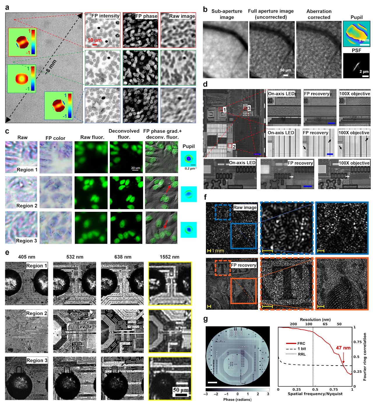
Fig. 5 Aberration metrology, surface inspection, long-range imaging, and X-ray nanoscopy via FP. a| Aberration recovery using a full-field model in FP62. b| In vivo eye imaging via CACAO-FB60. c| A multi-modal imaging system144, where the recovered aberration by FP is used to deconvolve the fluorescence image. d| Super-resolution surface inspection of a circuit board via reflected FP. A synthetic NA of 1.06 is achieved using a 10×, 0.28 NA objective106. e| Multispectral inspection of a silicon chip for fault detection via aperture-scanning FP. f| Long-range super-resolution imaging of a US bill via camera-scanning FP101. g| Super-resolution image of silicon chip via X-ray FP118.
5. Outlook
Real-space ptychography has become an indispensable imaging modality in most X-ray synchrotron laboratories worldwide. We anticipate that FP, currently in its early stage, will continue to grow and expand in applications. We identified the following areas for potential further developments of the FP approach.
Algorithms for blind FP reconstruction. Current challenging cases for blind FP reconstruction include specimens with many phase wraps (e.g. rough reflected surfaces), optical systems with severe unknown aberrations, light sources with low spatial and temporal coherence, measurements with interference fringe or other artefacts, and combinations of the above conditions. There have been attempts to convert the nonconvex phase retrieval problem to a convex optimization problem. One prominent example is PhaseLift145, which has been implemented in an FP setting72. In this approach, convex relaxation is needed to replace the rank constraint by a norm. For certain phase retrieval algorithms, it has been shown that the conditions guarantee the correspondence between the nonconvex problem and its convex relaxation are also sufficient to guarantee that the nonconvex problem does not have local minimums146. Therefore, recasting to convex relaxations may not necessarily give a better result compared to the nonconvex ones. The developments of memory-efficient nonconvex tools for handling these challenging cases are highly desired for the development of both FP and real-space ptychography.
Implementations of FP in the EUV regime. The adoption of 13.5 nm EUV lithography has become a new standard for manufacturing new generation of silicon chips. Identifying the defect in EUV mask is a challenging task and the related tools are among the most expensive ones in semiconductor fabrication facility. It is also important to perform the inspection at the same 13.5-nm wavelength since defects are often wavelength-sensitive. Early development has demonstrated the use of angle-varied illumination to improve the resolution107. We envision the lens translation strategy in X-ray FP can also be implemented for EUV light.
FP for chemical imaging. Infrared wavelengths contain vibration modes of many molecular bonds. The higher wavenumber region is associated with stretching vibrations such as S-H, C-H, N-H, and O-H, whereas the lower wavenumber regions typically correspond to bending and carbon skeleton fingerprint vibrations. Implementing FP in this region can find important applications in chemical imaging. A recent theoretical analysis has also shown the potential of applying FP for coherent anti-Stokes Raman scattering147. If successful, it can be an efficient approach for imaging thin tissue sections on specific Raman vibration transitions.
FP for electron microscopy. Current tilted-series method in electron microscopy acquires images under angle-varied illuminations. However, it performs image reconstruction using linear restoring filters26,27. The iterative phase retrieval process in FP can be employed in tilted series reconstruction for 2D thin specimens. Fourier ptychographic diffraction tomography124,127 or multi-slice modelling9,122,123 can be used to handle 3D specimens.
FP for education. The concept of FP can help students understand the basics of Fourier optics, including coherent transfer function, NA, pupil aberration, Ewald sphere, etc. The FP approach has become a sub-chapter in Goodman’s textbook “Introduction to Fourier Optics (4th edition)”. We envision the development of an FP microscope to be part of an optics lab course.
Other applications. Many FP applications remain to be seen. To name a few, the aberration metrology capability59,62,99 can be used to characterize the lens profile and the related optical transfer function. The high-throughput 96-camera platform109 can be used for drug screening. The QPI capability in 2D and 3D can be used to detect bloodborne and waterborne pathogens. Sample rotation can be integrated with the transmission X-ray FP for 3D nanoscopy. Diffraction tomography can be integrated with angle-varied illumination for imaging diffused reflective objects.
References:
1 Zheng, G., Horstmeyer, R. & Yang, C. Wide-field, high-resolution Fourier ptychographic microscopy. Nature photonics 7, 739 (2013).
2 Zheng, G., Kolner, C. & Yang, C. Microscopy refocusing and dark-field imaging by using a simple LED array. Optics letters 36, 3987-3989 (2011).
3 Zheng, G., Ou, X., Horstmeyer, R., Chung, J. & Yang, C. Fourier ptychographic microscopy: A gigapixel superscope for biomedicine. Optics and Photonics News 25, 26-33 (2014).
4 Ryle, M. & Hewish, A. The synthesis of large radio telescopes. Monthly Notices of the Royal Astronomical Society 120, 220-230 (1960).
5 Gerchberg, R. W. A practical algorithm for the determination of phase from image and diffraction plane pictures. Optik 35, 237-246 (1972).
6 Fienup, J. R. Phase retrieval algorithms: a comparison. Applied optics 21, 2758-2769 (1982).
7 Dong, S., Bian, Z., Shiradkar, R. & Zheng, G. Sparsely sampled Fourier ptychography. Optics Express 22, 5455-5464, doi:10.1364/OE.22.005455 (2014).
8 Song, P., Jiang, S. & Zheng, G. https://github.com/SmartImagingLabUConn/Fourier-Ptychography.
9 Li, P., Batey, D. J., Edo, T. B. & Rodenburg, J. M. Separation of three-dimensional scattering effects in tilt-series Fourier ptychography. Ultramicroscopy 158, 1-7 (2015).
10 Hoppe, W. & Strube, G. Diffraction in inhomogeneous primary wave fields. 2. Optical experiments for phase determination of lattice interferences. Acta Crystallogr. A 25, 502-507 (1969).
11 Faulkner, H. M. L. & Rodenburg, J. Movable aperture lensless transmission microscopy: a novel phase retrieval algorithm. Physical review letters 93, 023903 (2004).
12 Guizar-Sicairos, M. & Fienup, J. R. Phase retrieval with transverse translation diversity: a nonlinear optimization approach. Optics express 16, 7264-7278 (2008).
13 Thibault, P., Dierolf, M., Bunk, O., Menzel, A. & Pfeiffer, F. Probe retrieval in ptychographic coherent diffractive imaging. Ultramicroscopy 109, 338-343 (2009).
14 Maiden, A. M. & Rodenburg, J. M. An improved ptychographical phase retrieval algorithm for diffractive imaging. Ultramicroscopy 109, 1256-1262 (2009).
15 Dierolf, M. et al. Ptychographic X-ray computed tomography at the nanoscale. Nature 467, 436-439 (2010).
16 Maiden, A. M., Humphry, M. J., Zhang, F. & Rodenburg, J. M. Superresolution imaging via ptychography. JOSA A 28, 604-612 (2011).
17 Thibault, P. & Menzel, A. Reconstructing state mixtures from diffraction measurements. Nature 494, 68-71 (2013).
18 Batey, D. J., Claus, D. & Rodenburg, J. M. Information multiplexing in ptychography. Ultramicroscopy 138, 13-21 (2014).
19 Rodenburg, J. & Maiden, A. in Springer Handbook of Microscopy Ch. 17, 819-904 (Springer, 2019).
20 Horstmeyer, R. & Yang, C. A phase space model of Fourier ptychographic microscopy. Optics express 22, 338-358 (2014).
21 Li, P. & Maiden, A. Lensless LED matrix ptychographic microscope: problems and solutions. Applied optics 57, 1800-1806 (2018).
22 Maiden, A. M., Humphry, M. J. & Rodenburg, J. Ptychographic transmission microscopy in three dimensions using a multi-slice approach. JOSA A 29, 1606-1614 (2012).
23 Zhang, F. et al. Translation position determination in ptychographic coherent diffraction imaging. Optics express 21, 13592-13606 (2013).
24 Sun, J., Zuo, C., Zhang, L. & Chen, Q. Resolution-enhanced Fourier ptychographic microscopy based on high-numerical-aperture illuminations. Scientific reports 7, 1-11 (2017).
25 Song, P. et al. Super-resolved multispectral lensless microscopy via angle-tilted, wavelength-multiplexed ptychographic modulation. Optics Letters 45, 3486-3489 (2020).
26 Kirkland, A., Saxton, W., Chau, K.-L., Tsuno, K. & Kawasaki, M. Super-resolution by aperture synthesis: tilt series reconstruction in CTEM. Ultramicroscopy 57, 355-374 (1995).
27 Haigh, S. J., Sawada, H. & Kirkland, A. I. Atomic structure imaging beyond conventional resolution limits in the transmission electron microscope. Physical review letters 103, 126101 (2009).
28 Horstmeyer, R., Heintzmann, R., Popescu, G., Waller, L. & Yang, C. Standardizing the resolution claims for coherent microscopy. Nature Photonics 10, 68-71 (2016).
29 Ou, X., Horstmeyer, R., Zheng, G. & Yang, C. High numerical aperture Fourier ptychography: principle, implementation and characterization. Optics express 23, 3472-3491 (2015).
30 Sen, S., Ahmed, I., Aljubran, B., Bernussi, A. A. & de Peralta, L. G. Fourier ptychographic microscopy using an infrared-emitting hemispherical digital condenser. Applied optics 55, 6421-6427 (2016).
31 Pan, A. et al. Subwavelength resolution Fourier ptychography with hemispherical digital condensers. Optics express 26, 23119-23131 (2018).
32 Phillips, Z. F., Eckert, R. & Waller, L. in Imaging Systems and Applications. IW4E. 5 (Optical Society of America).
33 Bian, L. et al. Content adaptive illumination for Fourier ptychography. Optics letters 39, 6648-6651 (2014).
34 Zhang, Y., Jiang, W., Tian, L., Waller, L. & Dai, Q. Self-learning based Fourier ptychographic microscopy. Optics express 23, 18471-18486 (2015).
35 Li, S., Wang, Y., Wu, W. & Liang, Y. Predictive searching algorithm for Fourier ptychography. Journal of Optics 19, 125605 (2017).
36 Guo, K., Dong, S., Nanda, P. & Zheng, G. Optimization of sampling pattern and the design of Fourier ptychographic illuminator. Optics express 23, 6171-6180 (2015).
37 Dong, S., Shiradkar, R., Nanda, P. & Zheng, G. Spectral multiplexing and coherent-state decomposition in Fourier ptychographic imaging. Biomedical optics express 5, 1757-1767 (2014).
38 Tian, L., Li, X., Ramchandran, K. & Waller, L. Multiplexed coded illumination for Fourier Ptychography with an LED array microscope. Biomedical optics express 5, 2376-2389 (2014).
39 Zhou, Y. et al. Fourier ptychographic microscopy using wavelength multiplexing. Journal of biomedical optics 22, 066006 (2017).
40 Sun, J., Chen, Q., Zhang, J., Fan, Y. & Zuo, C. Single-shot quantitative phase microscopy based on color-multiplexed Fourier ptychography. Optics letters 43, 3365-3368 (2018).
41 Tian, L. et al. Computational illumination for high-speed in vitro Fourier ptychographic microscopy. Optica 2, 904-911 (2015).
42 Zhang, M., Zhang, L., Yang, D., Liu, H. & Liang, Y. Symmetrical illumination based extending depth of field in Fourier ptychographic microscopy. Optics express 27, 3583-3597 (2019).
43 Kuang, C. et al. Digital micromirror device-based laser-illumination Fourier ptychographic microscopy. Optics express 23, 26999-27010 (2015).
44 Chung, J., Lu, H., Ou, X., Zhou, H. & Yang, C. Wide-field Fourier ptychographic microscopy using laser illumination source. Biomedical optics express 7, 4787-4802 (2016).
45 Tao, X. et al. Tunable-illumination for laser Fourier ptychographic microscopy based on a background noise-reducing system. Optics Communications, 125764 (2020).
46 Guo, K. et al. Microscopy illumination engineering using a low-cost liquid crystal display. Biomedical optics express 6, 574-579 (2015).
47 Dong, S., Guo, K., Nanda, P., Shiradkar, R. & Zheng, G. FPscope: a field-portable high-resolution microscope using a cellphone lens. Biomedical optics express 5, 3305-3310 (2014).
48 Kamal, T., Yang, L. & Lee, W. M. In situ retrieval and correction of aberrations in moldless lenses using Fourier ptychography. Optics express 26, 2708-2719 (2018).
49 Aidukas, T., Eckert, R., Harvey, A. R., Waller, L. & Konda, P. C. Low-cost, sub-micron resolution, wide-field computational microscopy using opensource hardware. Scientific reports 9, 1-12 (2019).
50 Guo, C. et al. OpenWSI: a low-cost, high-throughput whole slide imaging system via single-frame autofocusing and open-source hardware. Optics Letters 45, 260-263 (2020).
51 Sun, J., Zuo, C., Zhang, J., Fan, Y. & Chen, Q. High-speed Fourier ptychographic microscopy based on programmable annular illuminations. Scientific reports 8, 1-12 (2018).
52 Bian, Z., Dong, S. & Zheng, G. Adaptive system correction for robust Fourier ptychographic imaging. Optics express 21, 32400-32410 (2013).
53 Pan, A. et al. System calibration method for Fourier ptychographic microscopy. Journal of biomedical optics 22, 096005 (2017).
54 Sun, J., Chen, Q., Zhang, Y. & Zuo, C. Efficient positional misalignment correction method for Fourier ptychographic microscopy. Biomedical optics express 7, 1336-1350 (2016).
55 Eckert, R., Phillips, Z. F. & Waller, L. Efficient illumination angle self-calibration in Fourier ptychography. Applied optics 57, 5434-5442 (2018).
56 Zhou, A. et al. Fast and robust misalignment correction of Fourier ptychographic microscopy for full field of view reconstruction. Optics express 26, 23661-23674 (2018).
57 Yeh, L.-H. et al. Experimental robustness of Fourier ptychography phase retrieval algorithms. Optics express 23, 33214-33240 (2015).
58 Liu, J. et al. Stable and robust frequency domain position compensation strategy for Fourier ptychographic microscopy. Optics Express 25, 28053-28067 (2017).
59 Ou, X., Zheng, G. & Yang, C. Embedded pupil function recovery for Fourier ptychographic microscopy. Optics express 22, 4960-4972 (2014).
60 Chung, J., Martinez, G. W., Lencioni, K. C., Sadda, S. R. & Yang, C. Computational aberration compensation by coded-aperture-based correction of aberration obtained from optical Fourier coding and blur estimation. Optica 6, 647-661 (2019).
61 Shen, C. et al. Computational aberration correction of VIS-NIR multispectral imaging microscopy based on Fourier ptychography. Optics express 27, 24923-24937 (2019).
62 Song, P. et al. Full-field Fourier ptychography (FFP): Spatially varying pupil modeling and its application for rapid field-dependent aberration metrology. APL Photonics 4, 050802 (2019).
63 Bian, L. et al. Motion-corrected Fourier ptychography. Biomedical optics express 7, 4543-4553 (2016).
64 Zhang, Y., Pan, A., Lei, M. & Yao, B. Data preprocessing methods for robust Fourier ptychographic microscopy. Optical Engineering 56, 123107 (2017).
65 Pan, A., Zuo, C., Xie, Y., Lei, M. & Yao, B. Vignetting effect in Fourier ptychographic microscopy. Optics and Lasers in Engineering 120, 40-48 (2019).
66 Zuo, C., Sun, J. & Chen, Q. Adaptive step-size strategy for noise-robust Fourier ptychographic microscopy. Optics express 24, 20724-20744 (2016).
67 Bian, L. et al. Fourier ptychographic reconstruction using Wirtinger flow optimization. Optics express 23, 4856-4866 (2015).
68 Bian, L. et al. Fourier ptychographic reconstruction using Poisson maximum likelihood and truncated Wirtinger gradient. Scientific reports 6, 27384 (2016).
69 Chen, S., Xu, T., Zhang, J., Wang, X. & Zhang, Y. Optimized denoising method for fourier ptychographic microscopy based on wirtinger flow. IEEE Photonics Journal 11, 1-14 (2019).
70 Bostan, E., Soltanolkotabi, M., Ren, D. & Waller, L. in 2018 25th IEEE International Conference on Image Processing (ICIP). 3823-3827 (IEEE).
71 Liu, J., Li, Y., Wang, W., Tan, J. & Liu, C. Accelerated and high-quality Fourier ptychographic method using a double truncated Wirtinger criteria. Optics express 26, 26556-26565 (2018).
72 Horstmeyer, R. et al. Solving ptychography with a convex relaxation. New journal of physics 17, 053044 (2015).
73 Zhang, Y., Song, P., Zhang, J. & Dai, Q. Fourier ptychographic microscopy with sparse representation. Scientific reports 7, 1-10 (2017).
74 Zhang, Y., Cui, Z., Zhang, J., Song, P. & Dai, Q. Group-based sparse representation for Fourier ptychography microscopy. Optics Communications 404, 55-61 (2017).
75 Zhang, Y., Song, P. & Dai, Q. Fourier ptychographic microscopy using a generalized Anscombe transform approximation of the mixed Poisson-Gaussian likelihood. Optics express 25, 168-179 (2017).
76 Fan, Y., Sun, J., Chen, Q., Wang, M. & Zuo, C. Adaptive denoising method for Fourier ptychographic microscopy. Optics Communications 404, 23-31 (2017).
77 Sun, Y. et al. in ICASSP 2019-2019 IEEE International Conference on Acoustics, Speech and Signal Processing (ICASSP). 7665-7669 (IEEE).
78 Jagatap, G., Chen, Z., Nayer, S., Hegde, C. & Vaswani, N. Sample efficient fourier ptychography for structured data. IEEE Transactions on Computational Imaging 6, 344-357 (2019).
79 Nguyen, T., Xue, Y., Li, Y., Tian, L. & Nehmetallah, G. Deep learning approach for Fourier ptychography microscopy. Optics express 26, 26470-26484 (2018).
80 Boominathan, L., Maniparambil, M., Gupta, H., Baburajan, R. & Mitra, K. Phase retrieval for Fourier Ptychography under varying amount of measurements. arXiv preprint arXiv:1805.03593 (2018).
81 Kappeler, A., Ghosh, S., Holloway, J., Cossairt, O. & Katsaggelos, A. in 2017 IEEE International Conference on Image Processing (ICIP). 1712-1716 (IEEE).
82 Xue, Y., Cheng, S., Li, Y. & Tian, L. Reliable deep-learning-based phase imaging with uncertainty quantification. Optica 6, 618-629 (2019).
83 Shamshad, F., Abbas, F. & Ahmed, A. in ICASSP 2019-2019 IEEE International Conference on Acoustics, Speech and Signal Processing (ICASSP). 7720-7724 (IEEE).
84 Zhang, J., Xu, T., Shen, Z., Qiao, Y. & Zhang, Y. Fourier ptychographic microscopy reconstruction with multiscale deep residual network. Optics express 27, 8612-8625 (2019).
85 Cheng, Y. F. et al. Illumination pattern design with deep learning for single-shot Fourier ptychographic microscopy. Optics express 27, 644-656 (2019).
86 Kellman, M. R., Bostan, E., Repina, N. A. & Waller, L. Physics-based learned design: optimized coded-illumination for quantitative phase imaging. IEEE Transactions on Computational Imaging 5, 344-353 (2019).
87 Muthumbi, A. et al. Learned sensing: jointly optimized microscope hardware for accurate image classification. Biomedical Optics Express 10, 6351-6369 (2019).
88 Horstmeyer, R., Chen, R. Y., Kappes, B. & Judkewitz, B. Convolutional neural networks that teach microscopes how to image. arXiv preprint arXiv:1709.07223 (2017).
89 Kellman, M., Bostan, E., Chen, M. & Waller, L. in 2019 IEEE International Conference on Computational Photography (ICCP). 1-8 (IEEE).
90 Jiang, S., Guo, K., Liao, J. & Zheng, G. Solving Fourier ptychographic imaging problems via neural network modeling and TensorFlow. Biomedical optics express 9, 3306-3319 (2018).
91 Sun, M. et al. Neural network model combined with pupil recovery for Fourier ptychographic microscopy. Optics Express 27, 24161-24174 (2019).
92 Zhang, Y. et al. PgNN: Physics-guided Neural Network for Fourier Ptychographic Microscopy. arXiv preprint arXiv:1909.08869 (2019).
93 Zhang, J. et al. Forward imaging neural network with correction of positional misalignment for Fourier ptychographic microscopy. Optics Express 28, 23164-23175 (2020).
94 Wang, R. et al. Virtual brightfield and fluorescence staining for Fourier ptychography via unsupervised deep learning. Optics Letters 45, 5405-5408, doi:10.1364/OL.400244 (2020).
95 Dong, S. et al. Aperture-scanning Fourier ptychography for 3D refocusing and super-resolution macroscopic imaging. Optics express 22, 13586-13599 (2014).
96 Choi, G.-J. et al. Dual-wavelength Fourier ptychography using a single LED. Optics letters 43, 3526-3529 (2018).
97 He, X., Jiang, Z., Kong, Y., Wang, S. & Liu, C. Fourier ptychography via wavefront modulation with a diffuser. Optics Communications 459, 125057 (2020).
98 Ou, X., Chung, J., Horstmeyer, R. & Yang, C. Aperture scanning Fourier ptychographic microscopy. Biomedical optics express 7, 3140-3150 (2016).
99 Horstmeyer, R., Ou, X., Chung, J., Zheng, G. & Yang, C. Overlapped Fourier coding for optical aberration removal. Optics express 22, 24062-24080 (2014).
100 He, X., Liu, C. & Zhu, J. Single-shot aperture-scanning Fourier ptychography. Optics express 26, 28187-28196 (2018).
101 Holloway, J., Wu, Y., Sharma, M. K., Cossairt, O. & Veeraraghavan, A. SAVI: Synthetic apertures for long-range, subdiffraction-limited visible imaging using Fourier ptychography. Science advances 3, e1602564 (2017).
102 Holloway, J. et al. Toward long-distance subdiffraction imaging using coherent camera arrays. IEEE Transactions on Computational Imaging 2, 251-265 (2016).
103 Guo, K., Dong, S. & Zheng, G. Fourier ptychography for brightfield, phase, darkfield, reflective, multi-slice, and fluorescence imaging. IEEE Journal of Selected Topics in Quantum Electronics 22, 77-88 (2015).
104 Pacheco, S., Salahieh, B., Milster, T., Rodriguez, J. J. & Liang, R. Transfer function analysis in epi-illumination Fourier ptychography. Optics letters 40, 5343-5346 (2015).
105 Pacheco, S., Zheng, G. & Liang, R. Reflective Fourier ptychography. Journal of biomedical optics 21, 026010 (2016).
106 Lee, H., Chon, B. H. & Ahn, H. K. Reflective Fourier ptychographic microscopy using a parabolic mirror. Optics Express 27, 34382-34391 (2019).
107 Wojdyla, A., Benk, M. P., Naulleau, P. P. & Goldberg, K. A. in Image Sensing Technologies: Materials, Devices, Systems, and Applications V. 106560W (International Society for Optics and Photonics).
108 Kim, J., Henley, B. M., Kim, C. H., Lester, H. A. & Yang, C. Incubator embedded cell culture imaging system (EmSight) based on Fourier ptychographic microscopy. Biomedical optics express 7, 3097-3110 (2016).
109 Chan, A. C. et al. Parallel Fourier ptychographic microscopy for high-throughput screening with 96 cameras (96 Eyes). Scientific reports 9, 1-12 (2019).
110 Konda, P. C., Taylor, J. M. & Harvey, A. R. Parallelized aperture synthesis using multi-aperture Fourier ptychographic microscopy. arXiv preprint arXiv:1806.02317 (2018).
111 He, X., Liu, C. & Zhu, J. Single-shot Fourier ptychography based on diffractive beam splitting. Optics letters 43, 214-217 (2018).
112 Lee, B. et al. Single-shot phase retrieval via Fourier ptychographic microscopy. Optica 5, 976-983 (2018).
113 Dong, S., Nanda, P., Shiradkar, R., Guo, K. & Zheng, G. High-resolution fluorescence imaging via pattern-illuminated Fourier ptychography. Optics express 22, 20856-20870 (2014).
114 Guo, K. et al. 13-fold resolution gain through turbid layer via translated unknown speckle illumination. Biomedical optics express 9, 260-275 (2018).
115 Yeh, L.-H., Chowdhury, S. & Waller, L. Computational structured illumination for high-content fluorescence and phase microscopy. Biomedical optics express 10, 1978-1998 (2019).
116 Zhang, H. et al. Near-field Fourier ptychography: super-resolution phase retrieval via speckle illumination. Optics express 27, 7498-7512 (2019).
117 Dong, S., Nanda, P., Guo, K., Liao, J. & Zheng, G. Incoherent Fourier ptychographic photography using structured light. Photonics Research 3, 19-23 (2015).
118 Wakonig, K. et al. X-ray Fourier ptychography. Science advances 5, eaav0282 (2019).
119 Detlefs, C., Beltran, M. A., Guigay, J.-P. & Simons, H. Translative lens-based full-field coherent X-ray imaging. Journal of Synchrotron Radiation 27 (2020).
120 Simons, H., Poulsen, H. F., Guigay, J. & Detlefs, C. X-ray Fourier ptychographic microscopy. arXiv preprint arXiv:1609.07513 (2016).
121 Pedersen, A. et al. X-ray coherent diffraction imaging with an objective lens: Towards three-dimensional mapping of thick polycrystals. Physical Review Research 2, 033031 (2020).
122 Tian, L. & Waller, L. 3D intensity and phase imaging from light field measurements in an LED array microscope. optica 2, 104-111 (2015).
123 Chowdhury, S. et al. High-resolution 3D refractive index microscopy of multiple-scattering samples from intensity images. Optica 6, 1211-1219 (2019).
124 Horstmeyer, R., Chung, J., Ou, X., Zheng, G. & Yang, C. Diffraction tomography with Fourier ptychography. Optica 3, 827-835 (2016).
125 Ling, R., Tahir, W., Lin, H.-Y., Lee, H. & Tian, L. High-throughput intensity diffraction tomography with a computational microscope. Biomedical optics express 9, 2130-2141 (2018).
126 Li, J. et al. High-speed in vitro intensity diffraction tomography. Advanced Photonics 1, 066004 (2019).
127 Zuo, C., Sun, J., Li, J., Asundi, A. & Chen, Q. Wide-field high-resolution 3D microscopy with Fourier ptychographic diffraction tomography. Optics and Lasers in Engineering 128, 106003 (2020).
128 Matlock, A. & Tian, L. High-throughput, volumetric quantitative phase imaging with multiplexed intensity diffraction tomography. Biomedical Optics Express 10, 6432 (2019).
129 Pham, T.-A. et al. Versatile reconstruction framework for diffraction tomography with intensity measurements and multiple scattering. Optics express 26, 2749-2763 (2018).
130 Song, P. et al. Super-resolution microscopy via ptychographic structured modulation of a diffuser. Optics letters 44, 3645-3648 (2019).
131 Bian, Z. et al. Ptychographic modulation engine: a low-cost DIY microscope add-on for coherent super-resolution imaging. Journal of Physics D: Applied Physics 53, 014005 (2019).
132 Tian, L. & Waller, L. Quantitative differential phase contrast imaging in an LED array microscope. Optics express 23, 11394-11403 (2015).
133 Aidukas, T., Konda, P. C., Harvey, A. R., Padgett, M. J. & Moreau, P.-A. Phase and amplitude imaging with quantum correlations through Fourier ptychography. Scientific reports 9, 1-9 (2019).
134 Zheng, G., Ou, X., Horstmeyer, R. & Yang, C. Characterization of spatially varying aberrations for wide field-of-view microscopy. Optics express 21, 15131-15143 (2013).
135 Yang, C., Qian, J., Schirotzek, A., Maia, F. & Marchesini, S. Iterative algorithms for ptychographic phase retrieval. arXiv preprint arXiv:1105.5628 (2011).
136 Baydin, A. G., Pearlmutter, B. A., Radul, A. A. & Siskind, J. M. Automatic differentiation in machine learning: a survey. The Journal of Machine Learning Research 18, 5595-5637 (2017).
137 Gustafsson, M. G. Surpassing the lateral resolution limit by a factor of two using structured illumination microscopy. Journal of microscopy 198, 82-87 (2000).
138 Cowley, J. M. & Moodie, A. F. The scattering of electrons by atoms and crystals. I. A new theoretical approach. Acta Crystallographica 10, 609-619 (1957).
139 Godden, T., Suman, R., Humphry, M., Rodenburg, J. & Maiden, A. Ptychographic microscope for three-dimensional imaging. Optics express 22, 12513-12523 (2014).
140 Ou, X., Horstmeyer, R., Yang, C. & Zheng, G. Quantitative phase imaging via Fourier ptychographic microscopy. Optics letters 38, 4845-4848 (2013).
141 Zheng, G. Breakthroughs in photonics 2013: Fourier ptychographic imaging. IEEE Photonics Journal 6, 1-7 (2014).
142 Horstmeyer, R., Ou, X., Zheng, G., Willems, P. & Yang, C. Digital pathology with Fourier ptychography. Computerized Medical Imaging and Graphics 42, 38-43 (2015).
143 Williams, A. J. et al. Fourier ptychographic microscopy for filtration-based circulating tumor cell enumeration and analysis. Journal of biomedical optics 19, 066007 (2014).
144 Chung, J., Kim, J., Ou, X., Horstmeyer, R. & Yang, C. Wide field-of-view fluorescence image deconvolution with aberration-estimation from Fourier ptychography. Biomedical optics express 7, 352-368 (2016).
145 Candes, E. J., Strohmer, T. & Voroninski, V. Phaselift: Exact and stable signal recovery from magnitude measurements via convex programming. Communications on Pure and Applied Mathematics 66, 1241-1274 (2013).
146 Hesse, R., Luke, D. R. & Neumann, P. Alternating projections and Douglas-Rachford for sparse affine feasibility. IEEE Transactions on Signal Processing 62, 4868-4881 (2014).
147 Heuke, S. et al. Coherent anti-Stokes Raman Fourier ptychography. Optics express 27, 23497-23514 (2019).
